So
You Want to Build a Dynamic Virtual Cockpit!
A Tutorial for Abacus Design Studio Pro
by J.P. Amodea

WARNING: This
tutorial shares something in common with air combat. It is 90% “setup” and 10% kill! But if you take the time to read the setup
discussion, you will be rewarded with all the information you require to build
a spectacular virtual cockpit, complete with active instrumentation and you
will pick up a few tricks along the way.
Table of Contents
Background
As it
turns out, you’ll be glad to know - that using only Design Studio Pro and a
simple text Editor like Notepad®, it isn’t really hard to
do at all!
A chicken
in every pot and a dynamic virtual cockpit for Everyman is what I say!
Let’s
agree first on two definitions. A static virtual cockpit is a 3D
cockpit within which you can pan around, but nothing moves and the instruments
are static or simple fixed images. A dynamic virtual cockpit is also a 3D
cockpit as above, but the instrumentation functions dynamically and there may
be animated parts as well, such as a moving stick or rudder pedals, etc.
Let’s
begin with a little background discussion
. . .
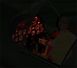
The
first time I remember experiencing such a virtual cockpit - with all the
needles and dials spinning around in virtual flight - was inside the cockpit of
the native Combat Flight Simulator aircraft.
It was then that I began to covet that kind of environment, some two
years and more ago now. I saw something
that I really wanted to have!
While I
took up the hobby of re-painting or texture art creation, I kept waiting to see
the first add-on with the DVC.
But we all waited in vain, didn’t we?
“It
must take some magic not available to the average wizards in the flightsim
community,” I thought. Some day perhaps,
sigh!
And
some day is here, thanks in good measure to Pentti Kurkinen.
Back in
November of 2000, I was substantially finished with my own first FSDS aircraft,
Schuftie, when I was all wrapped up in the wonder of the Multi-Resolution
model.
I
almost missed it . . .
I visit a number of sites
on a near-daily basis, and as far as 3D modeling for any of the Microsoft
flight simulator environments is concerned, you can’t find a better place than:
It was
there that I almost missed
it. The post by Pentti, announcing that
he was finishing up a tutorial on building CFS/CFS2 aircraft using a hybrid
system of constructing the individual parts with AF99®, but assembling them manually with SCASM coding and compilation
techniques. Within that tutorial
(available on line at the above site) you will find the essential knowledge
that, one weekend in November, I applied to my FSDS project, Schuftie.
At that
time, I resolved that this follow-up tutorial would be written just as soon as
I could get my then-current and then-overdue project released into cyberworld.
O.K.,
now we are ready to get serious!
Prerequisites
I am
going to assume that you are a 3D modeler “chomping at the bit” to do a DVC
yourself. Or perhaps you may be a
would-be modeler or CFS2 enthusiast who may be just on the cusp of a decision
to launch into a first project as well.
You’ll
also need to have some knowledge of how to build a conventional “flat” or 2D
panel.
You do
not have to be a panel maestro; you just need some passing knowledge of the
components and the interrelationships of these components.
What goes into a Dynamic Virtual Cockpit and how does
it work!
Inside
the cockpit, you will end up with just a few key elements.
You
will start with a part that will be labeled for external display only.
This part will be textured with a detailed representation of the cockpit
panel, but will only be visible from a point of view outside the aircraft. Here you want some good resolution.
Next,
typically, you will have two parts labeled vcockpit left and vcockpit right and
these will be textured as well and “tagged” in FSDS for internal view only. The
textures will be representations of the left and right half of the cockpit
panel and do not require high resolution.
I used only 128x128 pixel textures just like Microsoft used in their
native aircraft. Why wouldn’t you want
these to be high resolution as well?
You’ll have to read the rest of the tutorial to find out.
Next you will need the projection screen(s)!
By
this, I mean two square polygons that are sized properly for one half the
cockpit width each.
Don’t worry about the fact that to be square, they will “stick up” and
extend outside the boundaries of the cockpit.
Use a fully transparent polygon for each of these and label for internal view only.
The
remaining elements consist of the chosen gauges that will be automatically
selected from the sim’s gauges folder and the panel.cfg file that will instruct
the sim as to how to project the gauges onto the two projection screens.
Later,
as you read through the tutorial, you will learn how to make these elements
function to create your own dynamic virtual cockpit.
How it
works, we will get to as we go along.
The
Static View from Out in the Cold
If you
have already built an aircraft model with a static virtual cockpit, most
likely, you will have built a relatively flat panel out of a few - or perhaps
many polygons - and once satisfied with the final shape, you will have joined
the pieces to form a single part probably called something like “the panel.”
If you
want this static panel to be of high quality and if you want the dials and
gauges and labels to be read from outside of the aircraft, you would apply a
detailed texture that corresponds to a photograph of the internals of the
cockpit. To be readable, you will need
to use about ˝ the height of a 512x512 texture panel as a minimum.
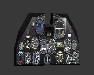
Here is
such an outside view of Schuftie:

And
below is an image of the particular texture that was used to achieve the above
result: Pay close attention to this
image capture of one of my textures, because there is a trick going on here
that we will come back to later! Can you figure out what I did?
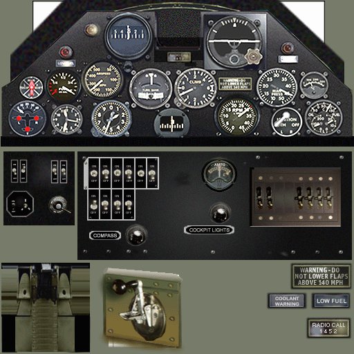
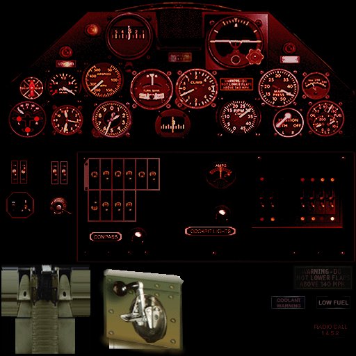
By the
way, don’t forget that FSDS and CFS2 support night textures. It is possible to duplicate the above texture
and adjust it and then rename it with a “_LM” appended to the texture name, and
this is what you get!
If this were not to be a dynamic virtual cockpit,
you would have tagged the part as visible within FSDS both external and also internal.
At that
point, you would be done!
Not any more!
You still need to do all this
“stuff,” but just tag it for external view.
This will be your static and highly detailed view when looking inside
the cockpit from a point of view outside the cockpit – “out in the cold.”
Panels
101 – Needed components for the DVC
I’ll
present some of the fundamental understandings first.
You
need all of the elements of a standard 2D panel as a start and you need a
platform within the 3D cockpit for display purposes.
What
are the elements of the 2D panel?
· Background graphic bitmap image.
· Collection of selected individual and/or “cluster” gauge files
· A panel.cfg file that serves as the text configuration file
containing instructions the sim needs to project these active gauges onto the
bitmap.
Those
of you who have built conventional panels know that the panel.cfg is “the
brains of the outfit.”
The
panel.cfg lists the individual gauges that are “borrowed” from the collection
of gauges in the gauges folder of the simulator and placed as an overlay upon
the bitmap. Each gauge entry consists of
a number or index, the name of the gauge file or portion of a multi-gauge or
“cluster” gauge file and three numerical values separated by commas.
The
numbers correspond with the “x” value or position from left to right; the “y”
value or position from top to bottom and a number which indicates the diameter
or size.
Let’s
look an example taken from the Kittyhawk Ia
Schuftie. The panel.cfg is opened using
Notepad®.
[Window00]
file=Panel_Background_640.BMP
file_1024=Panel_Background_1024.BMP
position=4
size_mm=640, 480
window_pos=0.0, 0.0
window_size=1.000, 1.000
render_3d_window=1
sizeable=1
visible=1
ident=MAIN_PANEL
gauge00=Spitfire_mkI!Heading_Indicator, 202, 270, 80
gauge01=P47d!Fuel_Warning, 131, 326, 23
gauge02=P47d!Gear, 51, 417, 62
gauge03=P38F_LIGHTNING!Left-Engine-Gauge, 521, 416, 61
gauge04=F4U1A_CORSAIR!Altimeter, 182, 416, 66
gauge05=F4F4_WILDCAT!Ignition-Switch, 468, 428, 51
gauge06=P38F_LIGHTNING!Attitude-Indicator, 366, 276, 88
gauge07=F6F3_HELLCAT!Climb_Indicator, 314, 363, 69
gauge08=F6F3_HELLCAT!CHT, 514, 369, 46
gauge09=A6M2_ZERO!Clock, 119, 424, 51
gauge10=F6F3_HELLCAT!Turn_Bank, 243, 364, 69
gauge11=F4F4_WILDCAT!Fuel-Selector, 69, 377, 38
gauge12=F4F4_WILDCAT!Manifold-Pressure, 444, 362, 68
gauge13=P-40E!Fuel, 107, 364, 59
gauge14=P-40E!Airspeed, 165, 346, 73
gauge15=P-40E!Compass,320, 435, 58
gauge16=P-40E!Tachometer, 378, 407, 74
gauge17=F4F4_Wildcat!Flaps-Lever,250, 440
gauge18=P-40E!Cowl_flaps, 165,315, 25
As it
is not within the scope of this tutorial to discuss all aspects of panel
design, we shall only make a quick study of the portion of the panel.cfg shown
above.
The
section entitled [window 00] defines the basic panel size and shape and
determines which bitmap file by name will be used as a background for the
panel. In some cases, as in the above,
two different resolution bitmaps are made available. The sim selects the appropriate one based
upon user screen resolution settings.
For our
purpose, you need only be concerned with the basic form of the entries for the
individual gauges. When we get down to
building the virtual cockpit, you will be making adjustments to a table similar
to the foregoing. Within the panel.cfg,
you will be adding your own table of values to instruct the sim where to
project the individual gauges within the virtual cockpit. The gauges will be individually numbered and
listed and the three numerical values will be entered to position the gauge and
size the gauge onto an invisible square polygon that will substitute for the
typical panel bitmap. There will also be
a bitmap or two or three needed to act as the background screen for the
projected gauges to overlay. More about this in greater detail later.
Below
is yet another excerpt from the panel.cfg of the Kittyhawk Ia
Schuftie. This excerpt represents the
complete portion of the file that determines the layout of the Dynamic Virtual
Cockpit. You will need to add such a
section to any companion panel.cfg that will accompany your own prospective
project.
[VCockpit01]
size_mm=256, 256
pixel_size=256,256
texture=$Schuftie_L
background_color=0,0,0
visible=0
gauge00=Spitfire_mkI!Heading_Indicator,
139, 33, 82,
gauge01=P47d!Fuel_Warning, 60, 91, 23
gauge02=P-40E!Cowl_flaps, 105, 80, 25
gauge03=F4F4_WILDCAT!Fuel-Selector, 12,
145, 38
gauge04=P-40E!Fuel, 49, 132, 59
gauge05=P-40E!Airspeed, 104, 115, 73
gauge06=F6F3_HELLCAT!Turn_Bank, 180,
132, 69
gauge07=F6F3_HELLCAT!Climb_Indicator,
250, 133, 69
gauge08=P47d!Gear, -03, 188, 62
gauge09=A6M2_ZERO!Clock, 63, 193, 51
gauge10=F4U1A_CORSAIR!Altimeter, 120,
186, 66
gauge11=P-40E!Compass,220, 200, 58
[VCockpit02]
size_mm=256,256
pixel_size=256,256
texture=$Schuftie_R
background_color=0,0,0
visible=0
gauge00=P38F_LIGHTNING!Attitude-Indicator,
35, 40, 88
gauge01=F6F3_HELLCAT!Climb_Indicator,
-04, 132, 69
gauge02=F4F4_WILDCAT!Manifold-Pressure,
118, 133, 68
gauge03=F6F3_HELLCAT!CHT, 188, 138, 46
gauge04=P-40E!Compass,-35, 200, 58
gauge05=P-40E!Tachometer, 56, 182, 74
gauge06=F4F4_WILDCAT!Ignition-Switch,
137, 201, 51
gauge07=P38F_LIGHTNING!Left-Engine-Gauge,
189, 188, 61
A quick
look at the above seems to suggest that there are two virtual cockpits?
Actually,
the DVC is divided into two squares each 256x256 pixels in size. What you are actually looking at is a
representation of the left half of the VC – [Vcockpit01] and the right half of
the VC - [Vcockpit02]
Why is
it desirable to section the cockpit into two or more squares?
Generally,
the cockpit surface where the gauges reside will be rectangular shape. Yes, you can make a single rectangular VC
panel, but you will have to work a lot harder if you do. The gauges are easiest to manipulate when they
are placed on a square surface. If you
place a gauge on an oblong surface, it assumes an oblong shape. It is possible to “square it back up” by
using a different kind of table of values.
Instead of a single third number for the size of the gauge, you will
need x-y coordinates and you will adjust the shape of the gauge to compensate
for the “stretching” caused by applying the gauge to a rectangular or oblong
surface. Why make things more difficult
for yourself?
Am I
being clear enough here? If you keep the
transparent projection screen surface perfectly square, the gauges stay
“squared” and they may be moved about and sized much more easily with the
simple three-number locating scheme as above.
“But,”
I hear you protest, “My cockpit has gauges right on or near the centerline or
gauges that span across the centerline.
How am I going to get the right effect with a seam down the middle?”
Well? You do not see any “stinking” seams in the
examples above do you?
As it
turns out, you can overlap the gauges in such a way that you have ˝ or 1/3 of a
gauge on one panel and the other ˝ or 2/3 of the gauge on the opposite
half. Isn’t that nice! Now you see why I illustrated a couple of the
gauge entries in this color above. You
may duplicate the gauge entries for gauges that fall on the seam, but you will
have to experiment with the x-y coordinates a little.
If you
want to get a feel for how the adjustments affect the position of the gauges in
the DVC, just move the numbers around for Schuftie a bit as an experiment.
I
confess to being a die-hard when it comes to panel design and panel work. I use the “trial and error” method using only
Notepad® to make adjustments.
Yes, there are a number of fine “drag and drop” graphic user interface
design aids out there for panel creation.
I believe a number of them work great, but you will need to manually
move the gauges anyway for the DVC.
As
mentioned earlier, the first entry is for the “x” position from left to
right. Low numbers are left and high
numbers are right. The second number is the “y” position from top to
bottom. Low numbers are near the top and
high numbers are near the bottom. The
third number is the diameter or overall size of the gauge.
O.K. Let’s do a recap.
You now
understand that you need to build your static virtual cockpit first within
FSDS. You need to label all the static
elements for external view only. You
realize that, to build a good dynamic virtual cockpit, you need to be familiar
with the panel.cfg file and you also need to work with the elements of the 2D
panel you have created or “borrowed” with permission.
Finally,
for now, you realize what pieces have to be built within the model for the
Dynamic Virtual Cockpit, but you haven’t done it yet and you don’t quite know
how to make it all work together.
Remember
my warning back up at the top of this tutorial?
It’s 90% setup and 10% kill. We
are now ready to go in for the kill!
Time
to Build the Dynamic Virtual Cockpit!
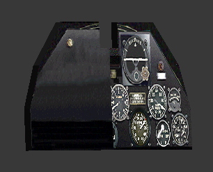
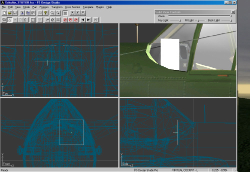
You
have completed building the static virtual cockpit. If we select only the 3D panel in FSDS that
has already been textured and tagged for external
view only, it might look something like the image below, left. FSDS shows all parts in the 3D view whether
tagged external, internal, or both.
 The next step is to duplicate this part and place
the new part in
exactly the same position as the
original one in the “x”
plane and the “y” plane,
but moved a few pixels
closer to the pilot viewpoint.
NOTICE! I chose to divide the part into a left
half and a right half,
though strictly speaking, you
could use a rectangular
shape. Using two square-like
shapes, however, enables
you to use two 128x128 pixel
square texture
panels. This is a more efficient approach
than using half a
256x256 pixel panel.
I
emulated Microsoft in employing this method.
The image capture to the right shows the original external
background with the new overlay part and only the left half in place.
The
easiest thing to do now would be to duplicate the left half using copy and
paste. Then flip the polygon in the “x”
plane and look at the part properties 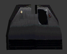 and change the sign of the “x” plane number so as to place the
part on the opposite side of the “z” axis.
I just described the easiest way I know to mirror a part.
and change the sign of the “x” plane number so as to place the
part on the opposite side of the “z” axis.
I just described the easiest way I know to mirror a part.
At this
point it is time to apply the texture for the right side and the image might
look something like what you see in the left side image capture.
You
will notice a little distortion in these images, because you are looking at a
3D view and the images are turned towards you from the perpendicular by about
60 degrees. Remember that the pair of
textured parts that overlay the external view must be tagged in FSDS for internal view only.
Hint: You should consider using an image capture of
your 2D panel for both the static background for the external view and you
should edit this same bitmap, removing all the gauges and then split the bitmap
in half vertically to have a consistent appearance. Remember to use the “V” operation to snap the
left and right edges together for the two internal panel background polygons so
that you avoid having an unsightly seam.
Time for the magic!
You
will now add two more perfectly square polygons that will act as projection screens
for the gauges themselves. As we
discussed earlier, a square projection surface will keep the gauges from
becoming distorted in shape. These two
polygons will once again be placed a few pixels closer to the pilot point of
view. You will want to check the
polygons in the polygon mode to ensure that the surface normals are facing your
pilot. I advise setting the properties
of these two parts as fully-transparent , opacity = to
0. Make sure you tag these polygons for internal view only.
I have noticed
that, with parts such as propeller disks and cockpit parts which are viewed
immediately upon start-up, that the unsightly solid
coloration experienced while the textures load, may be eliminated entirely.

You
have built a sandwich and it should now look something like what you see on the
left. Both polygons are present. The inside edges have been “snapped’ to avoid
a seam. The polygons overlap the
cockpit, but this will not matter as they will become transparent servants
whose only purpose in life is to serve as a kind of “glass” surface upon which
the gauges will be applied as a kind of dynamic decal.
You’ll
find a more complete presentation below.
Note that only the left side polygon is visible because it is selected,
whereas the right side is not selected and is consequently fully-transparent.
If you
were to stop here, you’d have a rather uninspiring bitmap background and no
gauges. Let’s add the gauges, shall
we?
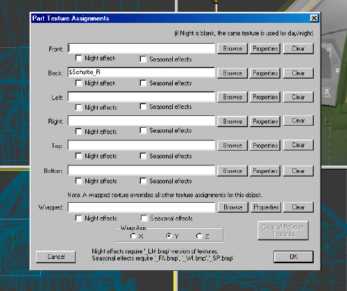
The
next step is to select the left half or right half of the projection
screen. Here we happen to have selected
the right side first. Once the part is
selected, choose to texture the part.
For the first time, you are going to enter a variable instead of a
texture panel name in the BACK texture field.
The name is unimportant, so long as it begins with the $ and specifies
the name that you will use for the [VCockpit01] or corresponding [VCockpit02]
in the panel.cfg file.
This
entry establishes the connection between the data that is entered in the panel.cfg
and the model or MDL file created by FSDS.
A little further experimentation may be necessary. In several attempts, I managed to “get it
right” each time. If you were to compile
the model at this point and if you had the data correct in the panel.cfg, the
gauges may be upside down and backwards.
With
the advent of FSDS version 1.5b, Louis Sinclair has simplified the required
adjustments to get the orientation correct for the gauges. Select the Properties button for the BACK
texture and you will bring up the next screen:
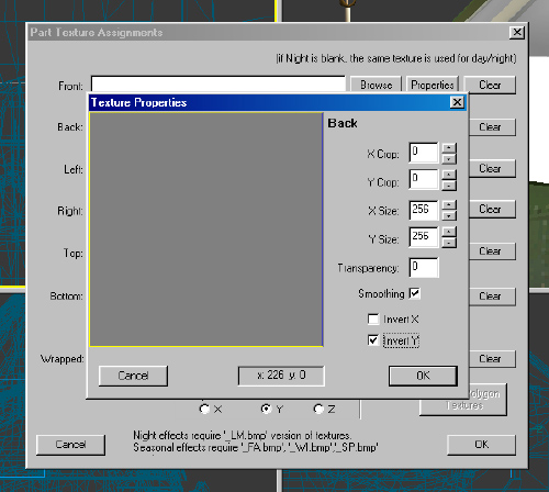
In this screen, begin by checking the “Invert Y” parameter. This should get the proper result for you on
the first try. If not, you could see
something like this:
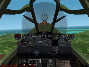
Well . . .
To get to
see the result of your handiwork, you must compile the model and go flying for
a bit. In the above screen, I have done
what you will most probably do. For the
initial test, I did not bother to apply the animations. They can wait until you are satisfied with
your new 3D Dynamic Virtual Cockpit.
If, in
spite of inverting the “Y” texture application, you do not get the correct
gauge orientation left to right and top to bottom, you may need to try another
alternate checkbox setting.
At this
point you have to prepare yourself for a little tedium.
I’ve
made one part of the process appear a bit easier than it really is. Your gauges will not be lined up properly at
this point. They will be there alright and they will be
functional, but they will be in a bit of a mess until you align them into
position with the old tried and true trial and error method.
Pull
your socks up now it isn’t as bad as all that.
You may
start by drawing the panel on a piece of paper and making an educated guess as
to where each gauge may go. If you have
made a 2D panel, then you know the drill.
Top to bottom, the lower number is closest to the top. Left to right, the lower number is to the
left. You’ll have to make an educated
guess for each gauge and you will have no difficulty lining up the correct
gauge sequence both vertically and horizontally, will you?
Here is
a trick that will save you a lot of time.
It’s an old trick for panel builders.
· Start the game and go flying with your new masterpiece.
· Pick a gauge that you would like to move.
· End the flight, but do not get out of the game.
· Switch to a different plane choice in your hangar, but don’t
start up.
· Open the panel.cfg.
· Make the change.
· Re-save the panel.cfg.
· Re-select your masterpiece
· Go flying again.
At this
point you may leave the panel.cfg
open with Notepad® and you may toggle the
process of ending the flight without quitting the game, temporarily reselecting
another aircraft; adjusting the panel.cfg
and resaving and you’re flying again!
Maybe
there is a better way to do this part?
If so, let me know and I will turn you into a star!
You
have finished your Dynamic Virtual Cockpit now, haven’t you?
Not
quite. I have one more trick up my
sleeve.
Do you
remember ages and ages ago that I asked you to look at my static cockpit
texture and I indicated that there was a trick at work there?
Have
you figured it out?
Brilliant! Then you have already realized that I have
used decals to add even more detail quality to the virtual cockpit, haven’t
you!
We’ve
got some good-looking active gauges; we’ve got a reasonably good background
texture that is 256 pixels wide and 128 pixels high when considering the left
and right halves. Why didn’t I go for
another 512x512 texture? It wasn’t
necessary because of the decals.
If you
look at the texture, you will see in the lower right corner, some
high-resolution images of the flaps warning, the coolant warning, low fuel and
radio call. These were each applied as
separate textures to each of four polygons used as decal overlays a pixel or
two closer to the pilot point of view than the low-res 128x128 texture
panels. Neat trick, eh?
I don’t
know about you, but I am ready for a break!
You’ll
have a tremendous amount of fun with this once you get the hang of it and it
isn’t really all that difficult.
Drop me
a line if you have any comments of if you have figured out a better way to do
any of this. I would be pleased to
update this tutorial from time to time and I will happily mention the source of
any new, good ideas.
Enjoy!
Joe
Amodea
February,
2001